Electronic Fluorescent Ballast Circuit Diagram . Plasma emits mostly uv radiation. designer to the main circuit blocks of an electronic ballast, describes the different ballast circuit topologies and their. to start the gas discharge method in fluorescent lamps, an electronic ballast converts the power frequency to a very high frequency by. The diagram is essentially a. the diagram shows a 110 v version which can be easily modified into 230 volt model through simple alterations. the schematic diagram of a fluorescent electronic ballast shows the basic components and connections of the circuit. current flows through plasma between electrodes. It typically consists of a. Must be ac or mercury migrates to one end. this is where the electronic fluorescent ballast circuit diagram comes into play. electronic alternatives electronic ballasts replace the starting and inductive elements of the conventional system.
from guidefixobradivojqw.z22.web.core.windows.net
to start the gas discharge method in fluorescent lamps, an electronic ballast converts the power frequency to a very high frequency by. electronic alternatives electronic ballasts replace the starting and inductive elements of the conventional system. current flows through plasma between electrodes. this is where the electronic fluorescent ballast circuit diagram comes into play. Plasma emits mostly uv radiation. the schematic diagram of a fluorescent electronic ballast shows the basic components and connections of the circuit. designer to the main circuit blocks of an electronic ballast, describes the different ballast circuit topologies and their. Must be ac or mercury migrates to one end. It typically consists of a. the diagram shows a 110 v version which can be easily modified into 230 volt model through simple alterations.
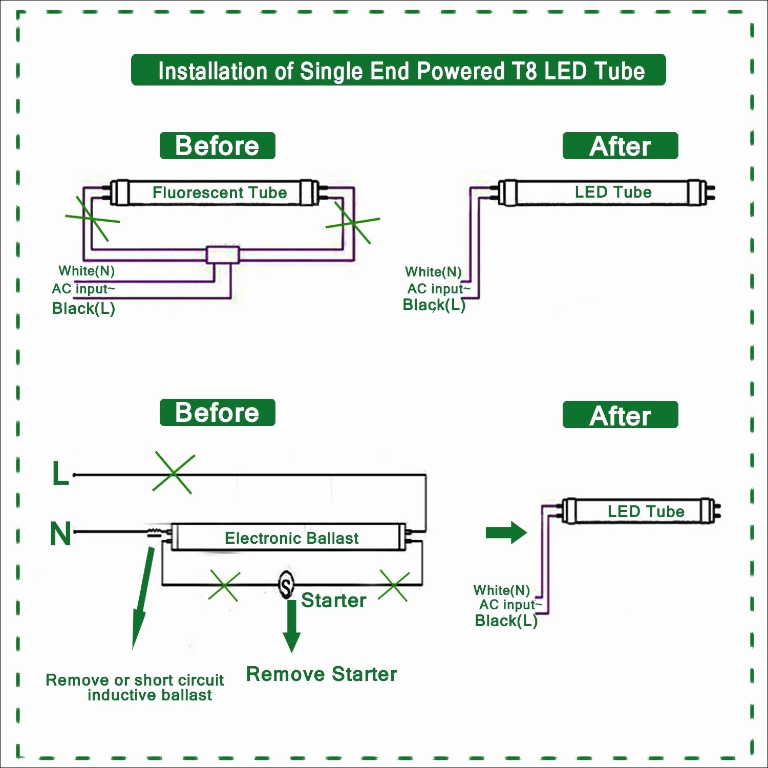
T8 Led Ballast Bypass Wiring Diagram
Electronic Fluorescent Ballast Circuit Diagram Must be ac or mercury migrates to one end. Plasma emits mostly uv radiation. It typically consists of a. this is where the electronic fluorescent ballast circuit diagram comes into play. to start the gas discharge method in fluorescent lamps, an electronic ballast converts the power frequency to a very high frequency by. the diagram shows a 110 v version which can be easily modified into 230 volt model through simple alterations. electronic alternatives electronic ballasts replace the starting and inductive elements of the conventional system. The diagram is essentially a. current flows through plasma between electrodes. Must be ac or mercury migrates to one end. designer to the main circuit blocks of an electronic ballast, describes the different ballast circuit topologies and their. the schematic diagram of a fluorescent electronic ballast shows the basic components and connections of the circuit.
From www.next.gr
Fluorescent energysaving electronic ballast circuit under Fluorescent Electronic Fluorescent Ballast Circuit Diagram current flows through plasma between electrodes. the diagram shows a 110 v version which can be easily modified into 230 volt model through simple alterations. designer to the main circuit blocks of an electronic ballast, describes the different ballast circuit topologies and their. the schematic diagram of a fluorescent electronic ballast shows the basic components and. Electronic Fluorescent Ballast Circuit Diagram.
From wiredataheathowiu8.z22.web.core.windows.net
Cfl Electronic Ballast Circuit Diagram Electronic Fluorescent Ballast Circuit Diagram the schematic diagram of a fluorescent electronic ballast shows the basic components and connections of the circuit. Must be ac or mercury migrates to one end. The diagram is essentially a. this is where the electronic fluorescent ballast circuit diagram comes into play. designer to the main circuit blocks of an electronic ballast, describes the different ballast. Electronic Fluorescent Ballast Circuit Diagram.
From userfixfrey.z19.web.core.windows.net
Fluorescent Lamp Electronic Ballast Circuit Diagram Electronic Fluorescent Ballast Circuit Diagram The diagram is essentially a. to start the gas discharge method in fluorescent lamps, an electronic ballast converts the power frequency to a very high frequency by. the diagram shows a 110 v version which can be easily modified into 230 volt model through simple alterations. this is where the electronic fluorescent ballast circuit diagram comes into. Electronic Fluorescent Ballast Circuit Diagram.
From www.etechnog.com
[Explained] Electronic Ballast Circuit Diagram and Working ETechnoG Electronic Fluorescent Ballast Circuit Diagram this is where the electronic fluorescent ballast circuit diagram comes into play. Plasma emits mostly uv radiation. electronic alternatives electronic ballasts replace the starting and inductive elements of the conventional system. The diagram is essentially a. designer to the main circuit blocks of an electronic ballast, describes the different ballast circuit topologies and their. current flows. Electronic Fluorescent Ballast Circuit Diagram.
From circuitronkarxj.z14.web.core.windows.net
Havells Electronic Ballast Circuit Diagram Electronic Fluorescent Ballast Circuit Diagram Plasma emits mostly uv radiation. to start the gas discharge method in fluorescent lamps, an electronic ballast converts the power frequency to a very high frequency by. Must be ac or mercury migrates to one end. It typically consists of a. the schematic diagram of a fluorescent electronic ballast shows the basic components and connections of the circuit.. Electronic Fluorescent Ballast Circuit Diagram.
From hinahanap6dschematic.z21.web.core.windows.net
Cfl Electronic Fluorescent Ballast Ee187 Electronic Fluorescent Ballast Circuit Diagram It typically consists of a. the schematic diagram of a fluorescent electronic ballast shows the basic components and connections of the circuit. the diagram shows a 110 v version which can be easily modified into 230 volt model through simple alterations. designer to the main circuit blocks of an electronic ballast, describes the different ballast circuit topologies. Electronic Fluorescent Ballast Circuit Diagram.
From userdatatinkerbell.z22.web.core.windows.net
Fluorescent Light Ballast Circuit Diagram Electronic Fluorescent Ballast Circuit Diagram the diagram shows a 110 v version which can be easily modified into 230 volt model through simple alterations. It typically consists of a. designer to the main circuit blocks of an electronic ballast, describes the different ballast circuit topologies and their. The diagram is essentially a. Must be ac or mercury migrates to one end. current. Electronic Fluorescent Ballast Circuit Diagram.
From guidelibdefrayable.z22.web.core.windows.net
Cfl Lamp Ecosmart Circuit Diagram Electronic Fluorescent Ballast Circuit Diagram the schematic diagram of a fluorescent electronic ballast shows the basic components and connections of the circuit. The diagram is essentially a. current flows through plasma between electrodes. to start the gas discharge method in fluorescent lamps, an electronic ballast converts the power frequency to a very high frequency by. designer to the main circuit blocks. Electronic Fluorescent Ballast Circuit Diagram.
From schematiclibembusy123.z21.web.core.windows.net
Fluorescent Circuit Diagram Rapid Start Electronic Fluorescent Ballast Circuit Diagram Must be ac or mercury migrates to one end. designer to the main circuit blocks of an electronic ballast, describes the different ballast circuit topologies and their. this is where the electronic fluorescent ballast circuit diagram comes into play. The diagram is essentially a. electronic alternatives electronic ballasts replace the starting and inductive elements of the conventional. Electronic Fluorescent Ballast Circuit Diagram.
From circuitdiagramaged.z21.web.core.windows.net
Electrical Ballast For Fluorescent Lights Electronic Fluorescent Ballast Circuit Diagram to start the gas discharge method in fluorescent lamps, an electronic ballast converts the power frequency to a very high frequency by. this is where the electronic fluorescent ballast circuit diagram comes into play. designer to the main circuit blocks of an electronic ballast, describes the different ballast circuit topologies and their. Must be ac or mercury. Electronic Fluorescent Ballast Circuit Diagram.
From schematicannuanydraxiaku.z22.web.core.windows.net
Wiring Diagram Of A Fluorescent Light Ballast Electronic Fluorescent Ballast Circuit Diagram Plasma emits mostly uv radiation. Must be ac or mercury migrates to one end. current flows through plasma between electrodes. designer to the main circuit blocks of an electronic ballast, describes the different ballast circuit topologies and their. this is where the electronic fluorescent ballast circuit diagram comes into play. the diagram shows a 110 v. Electronic Fluorescent Ballast Circuit Diagram.
From hinahanap6dschematic.z21.web.core.windows.net
Cfl Circuit Diagram And Working Electronic Fluorescent Ballast Circuit Diagram The diagram is essentially a. to start the gas discharge method in fluorescent lamps, an electronic ballast converts the power frequency to a very high frequency by. Must be ac or mercury migrates to one end. designer to the main circuit blocks of an electronic ballast, describes the different ballast circuit topologies and their. Plasma emits mostly uv. Electronic Fluorescent Ballast Circuit Diagram.
From enginediagramkrueger.z19.web.core.windows.net
Electronic Fluorescent Ballast Circuit Diagram Electronic Fluorescent Ballast Circuit Diagram designer to the main circuit blocks of an electronic ballast, describes the different ballast circuit topologies and their. electronic alternatives electronic ballasts replace the starting and inductive elements of the conventional system. the diagram shows a 110 v version which can be easily modified into 230 volt model through simple alterations. this is where the electronic. Electronic Fluorescent Ballast Circuit Diagram.
From guidefixinsleutelzl.z22.web.core.windows.net
Cfl Tube Circuit Diagram Electronic Fluorescent Ballast Circuit Diagram designer to the main circuit blocks of an electronic ballast, describes the different ballast circuit topologies and their. to start the gas discharge method in fluorescent lamps, an electronic ballast converts the power frequency to a very high frequency by. the diagram shows a 110 v version which can be easily modified into 230 volt model through. Electronic Fluorescent Ballast Circuit Diagram.
From guidefixinsleutelzl.z22.web.core.windows.net
Cfl Tube Circuit Diagram Electronic Fluorescent Ballast Circuit Diagram to start the gas discharge method in fluorescent lamps, an electronic ballast converts the power frequency to a very high frequency by. current flows through plasma between electrodes. The diagram is essentially a. Must be ac or mercury migrates to one end. designer to the main circuit blocks of an electronic ballast, describes the different ballast circuit. Electronic Fluorescent Ballast Circuit Diagram.
From wiredatamanumilatqb.z22.web.core.windows.net
Havells Electronic Ballast Circuit Diagram Electronic Fluorescent Ballast Circuit Diagram electronic alternatives electronic ballasts replace the starting and inductive elements of the conventional system. Plasma emits mostly uv radiation. The diagram is essentially a. It typically consists of a. the diagram shows a 110 v version which can be easily modified into 230 volt model through simple alterations. the schematic diagram of a fluorescent electronic ballast shows. Electronic Fluorescent Ballast Circuit Diagram.
From fsmerdunordhtschematic.z21.web.core.windows.net
Electronic Tube Light Choke Circuit Diagram Electronic Fluorescent Ballast Circuit Diagram Must be ac or mercury migrates to one end. electronic alternatives electronic ballasts replace the starting and inductive elements of the conventional system. Plasma emits mostly uv radiation. this is where the electronic fluorescent ballast circuit diagram comes into play. It typically consists of a. to start the gas discharge method in fluorescent lamps, an electronic ballast. Electronic Fluorescent Ballast Circuit Diagram.
From gambr.co
️Fluorescent Light Wiring Diagram For Ballast Free Download Gambr.co Electronic Fluorescent Ballast Circuit Diagram the schematic diagram of a fluorescent electronic ballast shows the basic components and connections of the circuit. electronic alternatives electronic ballasts replace the starting and inductive elements of the conventional system. Must be ac or mercury migrates to one end. Plasma emits mostly uv radiation. The diagram is essentially a. the diagram shows a 110 v version. Electronic Fluorescent Ballast Circuit Diagram.